Product Description
Requires Harness#’s: 802-4 or 802-4-S or 802-6 or SKT-11
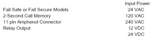
Each model is input power specific. Please specify input power when ordering.
11 pin rear “Amphenol” connector.
Advanced Diagnostics: Low Voltage, Open Loop, and Shorted Loop Conditions.
Automatic Reset Internal Fuse (24 VAC versions only), provides fuse & circuit protection.
Detect Memory helps prevent detection drops during short power interruptions.
Sensitivity Boost, for gate operation where high profile vehicles might be encountered.
2-Second CALL Delay.
Single Programmable relay offers selectable modes of operation:
True Presence™ (Infinite) or Limited Presence.
or Pulse on Entry or Pulse on Exit.
FAIL-SAFE and FAIL-SECURE versions available.
4 loop frequencies selectable from the front panel.
4 levels of sensitivity selectable from front panel.
Super bright LEDs provide separate power, DETECT, & loop FAIL indications.
Configurations available: 24 VAC, 120 VAC, 240 VAC, 12 VDC, & 24 VDC.
Single Channel Inductive Loop Vehicle Detectors
Features and benefits
11 pin rear “Amphenol” connector.
Advanced Diagnostics: Low Voltage, Open Loop, and Shorted Loop Conditions.
Automatic Reset Internal Fuse (24 VAC versions only), provides fuse & circuit protection.
Detect Memory helps prevent detection drops during short power interruptions.
Sensitivity Boost, for gate operation where high profile vehicles might be encountered.
2-Second CALL Delay.
Single Programmable relay offers selectable modes of operation:
True Presence™ (Infinite) or Limited Presence.
or Pulse on Entry or Pulse on Exit.
FAIL-SAFE and FAIL-SECURE versions available.
4 loop frequencies selectable from the front panel.
4 levels of sensitivity selectable from front panel.
Super bright LEDs provide separate power, DETECT, & loop FAIL indications.
Configurations available: 24 VAC, 120 VAC, 240 VAC, 12 VDC, & 24 VDC.
Model AX Series
Single Channel Inductive Loop Vehicle Detectors
Loop Frequency: Four frequencies (normally in the range of 20 to 100 kHz) are dip switch selectable from the front panel
Reset: Changing any dip switch position (except SW 1 & SW 2: frequency selection) will reset the detector. After changing the Frequency selection switches, the detector will require a RESET. Reset will clear the loop fault memory.
Sensitivity: Vehicle detection results when a negative change in loop inductance (ΔL/L) exceeds the sensitivity setting. Four detection sensitivity levels are dip switch selectable from the front panel.
Sensitivity
-ΔL/L
Low 0.32%
Med Lo 0.16%
Med Hi 0.08%
High 0.02%
Sensitivity Boost: An external dip switch setting may be turned on to increase sensitivity during the detect period. When a vehicle enters the loop, the detector sensitivity is boosted to a higher level than the vacant loop setting. The boosted sensitivity remains throughout the detect period. When the vehicle leaves the loop, the sensitivity returns to the vacant loop setting. This feature helps prevent dropouts during the passage of high bed vehicles and is particularly useful in sliding gate situations.
Output Configurations: The output is selectable for “TruePresence™” , “Limited Presence” , “Pulse on Entry” , or “Pulse on Exit”. TruePresence™ will hold the call for as long as the vehicle is present and power is not removed or reset applied. Limited presence will typically hold the CALL output for about 1-3 hours. The TruePresence™ time applies only for normal size automobiles and trucks and for normal size loops (approx. 12 sq. ft. to 120 sq. ft.). When in the pulse mode, the 250 millisecond pulse can be selected as either pulse on entry (when a vehicle enters the loop) or pulse on exit (when a vehicle exits the loop).
Call Delay: A 2-second delay can be activated by an internal dip switch. Output delay is the time the detector outputs are delayed after a vehicle first enters the loop detection area and is indicated by the front panel detect LED flashing at 4 Hz with a 50% duty cycle. If the 2-second output delay feature is activated, the output relays will only be turned on after 2 seconds has passed with a vehicle continuously present in the loop detection area. If a vehicle leaves the loop detection area during the 2-second delay interval, detection is aborted and the next vehicle entering the loop detection area will initiate a new full 2-second delay interval.
Output Call Memory: When power is removed for 2 seconds or less, the detector automatically “remembers” if a vehicle was present over the loop. When power is restored, the detector will continue to output a call until the vehicle leaves the loop. (Power loss or dips of 2 seconds or less will not drop the CALL).
Power Status Indicator: A green super-high-intensity light emitting diode (LED) indicates power status during normal detector operation. When the green (PWR) LED is on, the power to the detector is normal. When power drops approximately 20% from nominal, the green LED turns off and the detector remains operational. When power drops approximately 25% from nominal, the green LED is off and the “line” voltage is not sufficient to operate the detector
Detect Status Indicator: The red detect LED is steady on while a vehicle is being detected. The detect LED will flash at a 4 Hz rate with a 50% duty cycle while timing out the 2-Second Call Delay.
Loop FAIL Monitor Indicator: If the total inductance of the detector input network goes out of the range specified for the detector or suddenly changes more than +/-25% the detector will enter FAIL mode. The red FAIL LED will either begin flashing with a 50% duty cycle once per second for a shorted loop condition or will be on continuously for an open loop condition. These indicator conditions will continue until the inductance returns to its previous value at which time the detector output will automatically resume normal operation, and the red FAIL LED will flash at a distinctive rate (a burst of 3 flashes once per second) to indicate an intermittent loop fault has occurred and corrected. The flash rate will continue until another loop fault occurs, the detector is reset, or the detector loses power. [The detector input network, consists of the loop or loops plus the feeder cable (lead-in or home run) up to the connector on the detector].
Fail Safe Operation: When the loop fails or power is removed, continuity exists between Common & N.O. for presence mode. Continuity exists between Common & N.C. for pulse mode.
Fail Secure Operation: When the loop fails or power is removed, continuity exists between Common & N.C. for both presence and pulse modes.
Self Tuning: Automatically tunes to loop within 2 seconds after application of power or reset. 30 seconds of operation is required before full sensitivity and presence time is reached following application of power or a reset.
Environmental Tracking: Fully self-compensating for environmental changes and loop drift over the full temperature range and the entire loop inductance range.
Loop Inductance Range: 20 to 1000 µh with Q factor of 5 or greater.
Loop Feeder Length: Up to 2500 feet (762 m) maximum with proper feeder cable and appropriate loops.
Loop Input: Transformer isolated. The minimum capacitance added by the detector is 0.068 mF.
Grounded Loop Operation: The loop isolation transformer allows operation with poor quality loops (which may include a single point short, or leakage, to ground).
Lightning Protection: The detector can tolerate, without damage, a 10 mF capacitor charged to 1,000 Volts being discharged directly into the loop input terminals, or a 10 mF capacitor charged to 2,000 Volts being charged between either loop terminal and earth ground.
Internal Circuitry Isolation: All internal electronic circuitry is isolated from all external circuitry. Power is isolated by means of the power transformer. The loop is isolated by means of the loop isolation transformer. The outputs are isolated by means of the output relays.
Automatic Reset Internal Fuse: When 120VAC is applied to 24VAC models, the automatic internal fuse will open. The fuse will automatically reset when power is removed for 3 seconds. Source voltage should be verified before reinstalling.
Relay Rating(s): The relay contacts are rated for 6 Amp max, 150 VDC max, 300 VAC max and 180 Watts max switched power.
Ruggedized Construction: The enclosure is high temperature rated Lexan plastic. Printed circuit boards are 0.062 in FR4 material with double sided 2-oz copper and plated through-holes.
Operating Temperature: -40° F to + 180° F. Meets or exceeds NEMA specifications.
| Power(s): |
Fuse(s): |
| 18 to 32 VAC, 50/60 Hz., 4.0 Watts max |
24 VAC power: 120 mA, Polymeric |
| 89 to 135 VAC, 50/60 Hz., 4.0 Watts max |
120 VAC power: 3/8 Amp, Slo-Blo |
| 176 to 288 VAC., 50/60 Hz., 4.0 Watts max |
240 VAC power: 3/8 Amp, Slo-Blo |
| 10 to 16 VDC, 80 mA max |
12 VDC power: Current limited |
| 20 to 34 VDC, 50 mA max. |
24 VDC power: Current limited. |
Weight: Approx. 7.6 oz. (215.46 gm.).Size: 1.55 inches (3.90 cm.) Wide x 2.50 inches (6.35 cm.) High x 4.20 inches (10.65 cm.) Deep, including rear connector
Connector: 11 Pin Amphenol connector (86CP11)
Factory Default Settings (External DIP Switch):
Sensitivity Level: Med Lo
Output Configurations: Presence
Sensitivity Boost: OFF
Factory Default Settings (Internal DIP Switch):
True Presence™ (Infinite)
2-Second CALL Delay: OFF
| Models & Configurations |
|
Pin Assignments |
|
# |
Function |
| Model |
Voltage |
Operation |
1 |
Power, Hot or (+) |
| AX-3 |
120 VAC |
Fail Safe |
2 |
Power, Neutral or (-) |
| AX-3-S |
120 VAC |
Fail Secure |
3 |
No Connection |
| AX-7 |
24 VAC |
Fail Safe |
4 |
No Connection |
| AX-7-S |
24 VAC |
Fail Secure |
5 |
Output, Common (Com.) |
| AX-8 |
240 VAC |
Fail Safe |
6 |
Output, Normally Open (N.O) |
| AX-8-S |
240 VAC |
Fail Secure |
7 |
Loop |
| AX-23 |
12 VDC |
Fail Safe |
8 |
Loop |
| AX-23-S |
12 VDC |
Fail Secure |
9 |
No Connection |
| AX-24 |
24 VDC |
Fail Safe |
10 |
Output, Normally Closed (N.C.) |
| AX-24-S |
24 VDC |
Fail Secure |
11 |
No Connection |
Note: Relay contacts are shown with power applied, loop(s) connected, and no vehicles present.
Notes: CALL Memory is always on. There is no switch setting for this feature.
Please specify correct model number for FAIL-SAFE or FAIL-SECURE when ordering
** Specifications are subject to change to reflect improvements and upgrades.


