Preformed Saw Cut Style
Inductive Loop
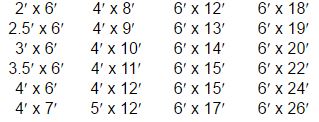
A wide selection of loop sizes and lead-in length in inventory and ready for shipment:


- Choice of XLP Insulations: Thin Wall (TW) & Std. 18 & 14 Ga. XLP.
- Non-spliced stock leads are 20′, 30′, 50′, 75′ & 100′.
- Custom size loops available.
- Custom non-spliced lead lengths.
Inductive Loop Installation
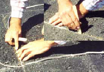
Mark out the loop area, using a construction crayon, to match the size and geometry of loop being installed. Exact measurements and saw cuts are not mandatory. However the more accurate, the easier the process becomes.
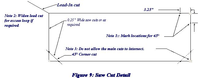
For the three corners with the 45° cuts, mark two points on each corner on the main cut lines 3.25″ away from the intersections that form the three corners. The 45° saw cut should intersect these points. (See fig. 9, Note 1)

If multiple loops are to be installed, you may elect to make a jig for establishing the position of the 45° cuts. Jig dimensions = 3.25″ X 3.25″ X 4.50″
On the corner without the 45° corner cut, mark the location and direction of the lead-in cut. In the event that the overall length of your saw cuts will not accommodate all of the Preformed Loop, for whatever reason, simply widen the home run / lead-in cut where it intersects the loop cut and install the excess loop into that cut. (See Fig.9, Note 2) You may fold or lap the excess loop in this wider cut without causing damage or changing the efficiency of the loop. Try to avoid extremely tight folds in the loop as this could cause the insulation or wires to break.
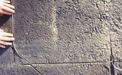
Make the cuts using a carbide or diamond tip blade designed for cutting concrete. Use a 0.25’’ wide blade, or multiple blades totaling 0.25‘’. Set the depth to a minimum of 1.50″. To prevent breakup of the pavement surface, do not let corners intersect when sawing the main loop cuts, except the corner for the Lead-in cut. (See Fig 9, Note 3) The loop will be installed in the 45° cuts and this will save cutting time.
When sawing the 45° corner cuts, cut approximately 1.0″ to 1.25″ past the loop cuts. This will maintain the saw cut depth through the 45° turns. Use a vacuum or air compressor to clean out the saw cuts.
Insert the loop and lead-in ensuring that the loop is at the bottom of the saw cut. Do not use a sharp or metal object to push the loop into the cuts. A tongue depressor will work well.
After the loop has been secured in the saw cut and the lead wires brought to the control box, make temporary connections as required and test the system. Assure that the lead wires will not vibrate or move during the test. If they do, it could cause erratic behavior in the system.
When the testing is complete and the system is operating correctly, seal the cuts with the properly mixed loop sealant for your temperature conditions. If any dirt or debris has entered the saw cut during testing, remove as required before sealing. Clean the excess sealer off the surface and allow the sealant to cure.


