Product Description
AX2 Single Connector Requires Harness #’s: 802-4-2TP or 802-4-2TP-S or SKT-11.
AX2 W/ 2 Connectors Requires Harness (2 each): 802-4 or 802-4-S.
Each model is input power specific. Please specify input power when ordering
Model AX2 & DL Series
Two-Channel Inductive Loop Vehicle Detectors
Features and benefits
All switches are accessible from the front panel.
Advanced Diagnostics: Low Voltage, Open Loop, and Shorted Loop Conditions.
Automatic Reset Internal Fuse (24 VAC versions only), provides fuse & circuit protection.
Power-Down Memory: When power is removed (no matter what length of time) the detector automatically determines the correct status of the loop when power is restored. Knows if vehicle enters or exits loop when power is down.
Directional Logic (AX2DL Series only) also know as AB Logic or BA logic uses the Ch. 1 (A) & Ch. 2 (B) loops to determine the direction the vehicle is traveling.
Sensitivity Boost, for gate operation where high profile vehicles might be encountered.
Single Programmable relays (per channel) offer selectable modes of operation:
True Presence™ (Infinite) or Pulse on Entry.
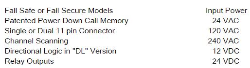
FAIL-SAFE and FAIL-SECURE versions available.
4 loop frequencies selectable from the front panel.
4 levels of sensitivity selectable from the front panel.
Super bright LEDs provide separate power, DETECT, & loop FAIL indications.
Single or Dual 11 pin rear “Amphenol” connectors.
Configurations available: 24 VAC, 120 VAC, 240 VAC, 12 VDC, & 24 VDC.
Model AX2 & DL Series
Two-Channel Inductive Loop Vehicle Detectors
Loop Frequency: There are 4 frequencies (normally in the range of 20 to 100 kHz) that are DIP switch selectable for each channel from the front panel. NOTE: Loops connected to channels 1 and 2 cannot crosstalk (loops are sequentially scanned). When loops are in close proximity to each other and connected to different detector units, it may be necessary to select different frequencies for each loop to avoid loop interference.
Reset: Reset button resets both channels. Changing any dip switch position (except SW 1 & SW 2: frequency selection) will reset the channel. After changing the Frequency selection switches, the detector will require a RESET. Reset will clear the loop fault memory.
Sensitivity: Vehicle detection results when a negative change in loop inductance (-ΔL/L) exceeds the sensitivity setting. Four detection sensitivity levels for each channel are front panel DIP switch selectable.
| Sensitivity |
-ΔL/L |
| 0 |
0.32% |
| 1 |
0.16% |
| 2 |
0.08% |
| 3 |
0.02% |
Sensitivity Boost: An external dip switch setting may be turned on to increase sensitivity during the detect period. When a vehicle enters the loop, the detector sensitivity is boosted to a higher level than the vacant loop setting. The boosted sensitivity remains throughout the detect period. When the vehicle leaves the loop, the sensitivity returns to the vacant loop setting. This feature helps prevent dropouts during the passage of high bed vehicles and is particularly useful in sliding gate situations.
Output Relay(s): The output is selectable for each channel for either “TruePresence ” or “Pulse on Entry”. TruePresence will hold the call for as long as the vehicle is present and power is not removed or reset applied. The TruePresence time applies only for normal size automobiles and trucks and for normal size loops (approx. 12 sq. ft. to 120 sq. ft.). The pulse (width) output is 250 milliseconds.
Directional Logic (AX2DL Series): Directional Logic, also known as AB Logic or BA Logic uses the Ch. 1 & Ch. 2 loops to determine the direction the vehicle is traveling. The loops must be spaced such that a vehicle can span both loops. The expected installation is two loops, one after the other in the same lane, spaced anywhere from overlapping to 6 feet apart. AB Logic is when a vehicle travels from Ch. 1 loop (A) and enters the Ch. 2 loop (B) (vehicle is now over both loops), activating the relay and LED on Ch. 2 to indicate the AB direction. BA Logic is when a vehicle travels from Ch. 2 loop (B) and enters the Ch. 1 loop (A), activating the relay and LED on Ch. 1 to indicate the BA direction.
Power Down Memory: When power is remove, the detector automatically “remembers” the operating parameters of the loop for each channel. During the loss of power, vehicles may enter or leave the loop area. When power is restored, the detector will determine if any vehicle is present in the loop and output a call if appropriate. IMPORTANT: After installing and applying power, momentarily push the RESET button to clear the Power Down Memory. This initializes the detector to the loops that are connected and clears the memory of any previous loop information.
Power Status Indicator: A green super-high-intensity light emitting diode (LED) indicates power status during normal detector operation. When the green (PWR) LED is on, the power to the detector is normal. When power drops approximately 20% from nominal, the green LED turns off and the detector remains operational. When power drops approximately 25% from nominal, the green LED is off and the “line” voltage is not sufficient to operate the detector.
Detect Status Indicator: The red detect LED is steady on while a vehicle is being detected.
Loop FAIL Monitor Indicator: If the total inductance of the detector input network goes out of the range specified for the detector or suddenly changes more than +/-25% the detector will enter FAIL mode. The red FAIL LED will either begin flashing with a 50% duty cycle once per second for a shorted loop condition or will be on continuously for an open loop condition. These indicator conditions will continue until the inductance returns to its previous value at which time the detector output will automatically resume normal operation, and the red FAIL LED will flash at a distinctive rate (a burst of 3 flashes once per second) to indicate an intermittent loop fault has occurred and corrected. The flash rate will continue until another loop fault occurs, the detector is RESET, or the detector loses power. [The detector input network, consists of the loop or loops plus the feeder cable (lead-in or home run) up to the connector on the detector].
Fail Safe Operation: When either Ch. 1 or Ch. 2 loop fails or power is removed, continuity exists between that channel’s Common & N.O..
Fail Secure Operation: When either Ch. 1 or Ch. 2 loop fails or power is removed, continuity exists between that channel’s Common & N.C.
Self Tuning: Automatically tunes to loop within 2 seconds after application of power or reset. 30 seconds of operation is required before full sensitivity and presence time is reached following application of power or a reset.
Environmental Tracking: Fully self-compensating for environmental changes and loop drift over the full temperature range and the entire loop inductance range.
Loop Inductance Range: 20 to 1000 µh with Q factor of 5 or greater.
Loop Input: Transformer isolated. The minimum capacitance added by the detector is 0.068 mF.
Grounded Loop Operation: The loop isolation transformer allows operation with poor quality loops (which may include a single point short, or leakage, to ground).
Lightning Protection: The detector can tolerate, without damage, a 10 mF capacitor charged to 1,000 Volts being discharged directly into the loop input terminals, or a 10 mF capacitor charged to 2,000 Volts being charged between either loop terminal and earth ground.
Internal Circuitry Isolation: All internal electronic circuitry is isolated from all external circuitry. Power is isolated by means of the power transformer. The loop is isolated by means of the loop isolation transformer. The outputs are isolated by means of the output relays.
Automatic Reset Internal Fuse: When 120VAC is applied to 24VAC models, the automatic internal fuse will open. The fuse will automatically reset when power is removed for 3 seconds. Source voltage should be verified before reinstalling.
Relay Rating(s): The relay contacts are rated for 2 Amp max, 60 VDC max, 120 VAC max and 30 Watts max switched power.
Ruggedized Construction: The enclosure is high temperature rated Lexan plastic. Printed circuit boards are double sided 2-oz copper with plated through-holes.
Operating Temperature: -40° F to + 180° F.
| Power(s): |
Fuse(s): |
| 18 to 32 VAC, 50/60 Hz., 4.0 Watts max |
24 VAC power: 120 mA, Polymeric |
| 89 to 135 VAC, 50/60 Hz., 4.0 Watts max |
120 VAC power: 3/8 Amp, Slo-Blo |
| 176 to 288 VAC., 50/60 Hz., 4.0 Watts max |
240 VAC power: 3/8 Amp, Slo-Blo |
| 10 to 16 VDC, 80 mA max |
12 VDC power: Current limited |
| 20 to 34 VDC, 50 mA max |
24 VDC power: Current limited |
Size: 1.75 inches (4.45 cm.) Wide x 3.00 inches (7.62 cm.) High x 5.00 inches (12.70 cm.) Deep, including rear connector.
Weight: Approx. 8.1 oz. (229.64 gm.).
Connector: Single or Dual rear mount 11 Pin male “Amphenol” connector (86CP11).
| Single 11 Pin Type |
| Normally Closed (NC) Outputs |
Normally Open (NO) Outputs |
| # |
Function |
# |
Function |
| 1 |
Power, Hot or (+) |
1 |
Power, Hot or (+) |
| 2 |
Power, Neutral or (-) |
2 |
Power, Neutral or (-) |
| 3 |
Relay Output Ch. 2, Normally Closed |
3 |
Relay Output Ch. 2, Normally Open |
| 4 |
No Connection |
4 |
No Connection |
| 5 |
Relay Output Ch. 1, Common |
5 |
Relay Output Ch. 1, Common |
| 6 |
Relay Output Ch. 1, Normally Closed |
6 |
Relay Output Ch. 1, Normally Open |
| 7 |
Ch. 1 Loop |
7 |
Ch. 1 Loop |
| 8 |
Ch. 1 Loop |
8 |
Ch. 1 Loop |
| 9 |
Relay Output Ch. 2, Common |
9 |
Relay Output Ch. 2, Common |
| 10 |
Ch. 2 Loop |
10 |
Ch. 2 Loop |
| 11 |
Ch. 2 Loop |
11 |
Ch. 2 Loop |
| Dual 11 Pin Type |
| Connector 1 (Upper) |
Connector 2 (Lower) |
| # |
Function |
# |
Function |
| 1 |
Power, Hot or (+) |
1 |
No Connection |
| 2 |
Power, Neutral or (-) |
2 |
No Connection |
| 3 |
No Connection |
3 |
No Connection |
| 4 |
No Connection |
4 |
No Connection |
| 5 |
Relay Output Ch. 1, Common |
5 |
Relay Output Ch. 2, Common |
| 6 |
Relay Output Ch. 1, Normally Open |
6 |
Relay Output Ch. 2, Normally Open |
| 7 |
Ch. 1 Loop |
7 |
Ch. 2 Loop |
| 8 |
Ch. 1 Loop |
8 |
Ch. 2 Loop |
| 9 |
No Connection |
9 |
No Connection |
| 10 |
Relay Output Ch. 1, Normally Closed |
10 |
Relay Output Ch. 2, Normally Closed |
| 11 |
No Connection |
11 |
No Connection |
| Note: * Relay contacts are shown with power applied, loop(s) connected, and no vehicles present. |
Factory Default Settings:
Sensitivity Level: Level 1
Output Configurations: Relay = True Presence™ (Infinite)
Sensitivity Boost: OFF
Frequency: HIGH
Notes:
* Power Down Memory is always on. There is no switch setting for this feature.
** Specifications are subject to change to reflect improvements and upgrades.


